
This would help if the board is stuck on some command. However, be prepared to occasionally ground the RST pin.
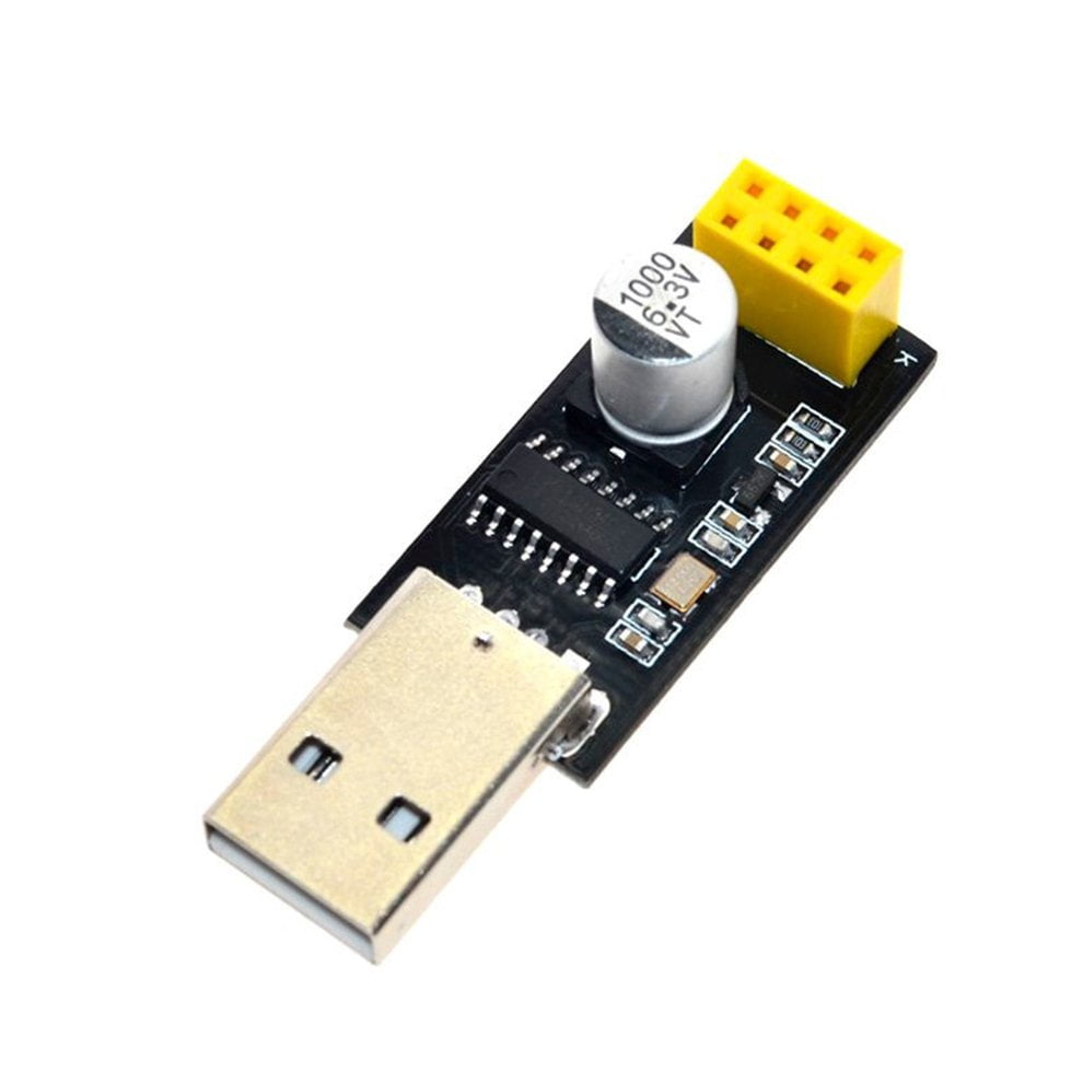
The rest of the pins should be floating. Note that it is possible to use an Arduino 3v3 supply for this. Connect a 3v3 power supply to the VCC/GND pins. Connect the RX/TX pins in a 3v3 FTDI cable to the TX/RX pins in the ESP module. Apparently, this is an error made by the manufacturer, so it might be corrected at some point. The current batch of the FTDI cables deliver 5V in the supply rail even for the 3V3 version. Note that the module is not designed for more than 3.6V, so a 3.3V power supply should be used - both for power and logic. An easy solution is to use a 3V3 FTDI cable. Testing the module via FTDI (or a USB-to-Serial cable)īefore connecting the module to a microcontroller, it's important to try it directly via a serial interface. Also, once the device is connected and is set to accept connections, it will send unsolicited messages whenever a new connection or a new request is issued. It then responds back with the operation's outcome (assuming everything is running correctly). The module accepts commands via a simple serial interface. 

It can also be easily configured as a web server.
#ESP8266 SERIAL PORT ADAPTER FULL#
The ESP8266 has a full TCP/UDP stack support. Once you are set up, you should learn more about the module's protocol here: Usageįirst, it is important to understand how the board works. In general, the tutorial below will get you started. A good example is how newer versions use 9600 baud rate, while older versions (by old I'm referring to 2-3 months old modules) used 57600-115200 baud rates. However, a word of caution - it is highly undocumented (primary reason for writing this document), and more importantly, it is frequently updated and not backward compatible. The ESP8266 is a low cost Serial-to-WiFi module that interfaces nicely to any microcontroller.


 0 kommentar(er)
